


When dealing with ASME B16.5 RF flanges, ensuring proper concentricity is crucial. As a well - established supplier of ASME B16.5 RF flanges, I understand the importance of this parameter in maintaining the integrity and efficiency of piping systems. In this blog, I will share the processes and methods to check the concentricity of these flanges.
Understanding ASME B16.5 RF Flanges
ASME B16.5 is a standard that defines the dimensions, tolerances, and other requirements for pipe flanges and flanged fittings. The "RF" stands for Raised Face, which is one of the most common face types for flanges. These flanges are used extensively in various industries such as oil and gas, chemical, and power generation. Different from the ASME B16.5 RTJ which has a ring - type joint, RF flanges provide a flat - gasket seating surface.
Why Concentricity Matters
Concentricity refers to the degree to which the center axis of one part aligns with the center axis of another part. In the case of ASME B16.5 RF flanges, proper concentricity ensures:
- Uniform Seal: A properly aligned flange will provide an even compression of the gasket, preventing leaks. Leaks in piping systems can lead to loss of product, safety hazards, and environmental problems.
- Long - term Durability: Misaligned flanges can cause uneven stress distribution on the bolts and the flange itself. Over time, this can lead to premature wear, fatigue, and failure of the flange connection.
- Ease of Assembly: Concentric flanges are easier to assemble, reducing installation time and labor costs.
Tools Required for Concentricity Check
Before starting the concentricity check, it is essential to gather the necessary tools. Here are some commonly used tools:
- Dial Indicator: A dial indicator is a precision instrument used to measure small linear distances. It can be used to determine the deviation of the flange's center from its ideal position.
- Magnetic Base: A magnetic base is used to securely hold the dial indicator in place during the measurement process. This ensures accurate and consistent readings.
- Straight Edge: A straight edge can be used to visually inspect the flange's face for any visible misalignment. It can also be used in conjunction with the dial indicator for more accurate measurements.
Step - by - Step Guide to Check Concentricity
Step 1: Preparation
- Clean the Flanges: Before starting the measurement, clean the flange faces thoroughly to remove any dirt, debris, or rust. This ensures accurate contact between the measurement tools and the flange surface.
- Mount the Flanges: If possible, mount the flanges on the pipes or test fixtures in the same way they will be installed in the actual system. Make sure the mounting is secure and free from any movement.
Step 2: Initial Visual Inspection
- Use a straight edge to visually check the flange faces. Place the straight edge across the flange's raised face and look for any gaps or unevenness. If there are significant gaps, it may indicate a problem with the flange's flatness or concentricity.
Step 3: Dial Indicator Installation
- Attach the dial indicator to the magnetic base. Place the magnetic base on a stable surface near the flange, ensuring that the indicator's probe can reach the flange's inner or outer diameter, depending on the method of measurement.
- For measuring the concentricity of the inner diameter, position the dial indicator's probe against the inner surface of the flange. Make sure the probe is perpendicular to the surface.
Step 4: Taking Measurements
- Rotate the flange slowly through a full 360 - degree rotation. As the flange rotates, the dial indicator will show the variation in the distance between the probe and the flange surface.
- Take readings at regular intervals, such as every 45 degrees. Record these readings accurately. The maximum and minimum readings will indicate the deviation from the ideal concentric position.
- For measuring the outer diameter, repeat the same process with the dial indicator probe placed against the outer surface of the flange.
Step 5: Analyzing the Results
- Calculate the difference between the maximum and minimum readings. This difference is the total indicated runout (TIR), which represents the degree of non - concentricity.
- Compare the TIR value with the allowable tolerances specified in the ASME B16.5 standard. If the TIR value exceeds the allowable tolerance, the flange may need to be re - machined or replaced.
Special Considerations for Different Flange Sizes
When dealing with RF Flange NPS 1/2~NPS24, different sizes may require different measurement techniques.
- Smaller Flanges (NPS 1/2 - NPS 6): For smaller flanges, it may be more challenging to use a dial indicator due to the limited space. In such cases, a precision micrometer or a bore gauge can be used to measure the inner or outer diameter at multiple points around the flange.
- Larger Flanges (NPS 8 - NPS 24): Larger flanges are more likely to have greater weight and size, which can cause deformation during handling. When checking the concentricity of larger flanges, it is important to ensure that the flanges are properly supported to prevent any additional misalignment.
Implications for Different Flange Types
While we focus on ASME B16.5 RF flanges, the concept of concentricity also applies to other flange types such as Weld Neck Flange. However, the measurement methods may vary slightly.

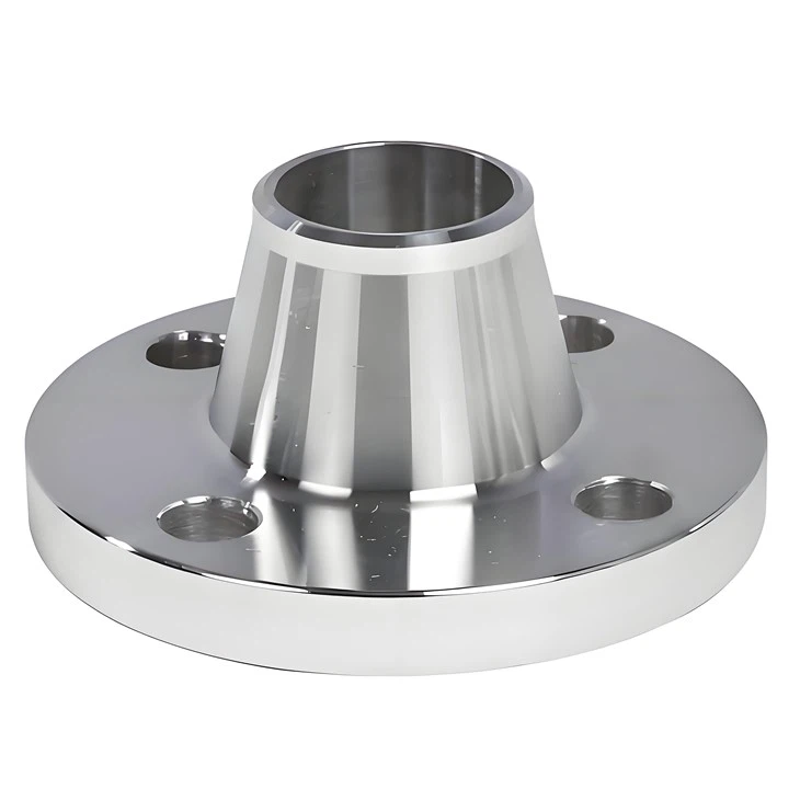
- Weld Neck Flanges: These flanges are welded to the pipe, which can introduce additional factors that affect concentricity. After welding, the weld integrity and the alignment of the welded joint need to be checked in addition to the flange's own concentricity.
Conclusion
Checking the concentricity of ASME B16.5 RF flanges is a critical process that ensures the reliability and performance of piping systems. By using the right tools and following the correct procedures, we can accurately measure the concentricity and take appropriate actions if any issues are detected.
If you are in the market for high - quality ASME B16.5 RF flanges and need further information or wish to discuss your procurement needs, feel free to reach out. Our team of experts is ready to assist you in selecting the right flanges and ensuring they meet your specific requirements.
References
- ASME B16.5 Standard for Pipe Flanges and Flanged Fittings
- Piping Handbook, various editions